Cooperative fire detection in Comets
The first step of the mission scenario is fire detection.
First, MARVIN follows a path while gathering sensor data with its fire sensor.
Once an alarm (or several alarms) are detected, HELIV is sent to confirm (or discard)
the alarm and localize it more precisely. Afterwards, in case of a confirmed alarm,
a monitoring phase is initiated.
|
Fire sensor as the "white nose" of MARVIN
|
All the vehicles are able to estimate their positions by different means (DGPS and others) in a
global coordinate frame. The position data label all the sensor data, and it will be used for
localization of the alarms.
The fire sensor data are processed to evolve a fire probability grid that covers the scenario.
Initially, each cell of this map is set to a probability of 0.5; that is, nothing is known about
the probability of having fire in a particular position. The cell size is about 5 meters, so that
is the maximum resolution in positioning using the grid.
|

Figure 1
|
Figure 2
|
|
Figure 3
|

Figure 4
|
|
Figure 5
|
From the grid, connected regions with high probability are extracted, computing their
mean position and their second order momenta (as a measure of the uncertainty of this mean position).
These regions are declared as possible fire alarms.
Then, the confirmation phase begins. During confirmation, Helivision infrared images are
processed. Each time a new image arrives, the current alarms are projected over the image
plane of the camera (using the positioning data that label the images). The alarms are
associated with the detected objects on the image (or discarded if no fire was detected
on the image in the position).
|

Infrared Fusion
|
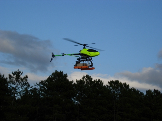
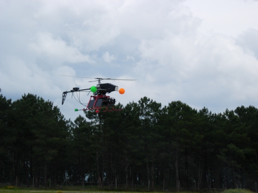
Helivision
|
The associated data are used to update the probability of being fire for each object,
and also to refine its estimated position.
In the example shown in the figures, three alarms are generated using the fire sensor data.
Then, the confirmation phase is able to discard the two false alarms. Also, the position of
the alarm is iteratively updated. Finally, the position of the alarm is determined with
a precision close to one meter.
|
|
Easting
|
Northing
|
Height
|
|
Measured position of the fire
|
564627
|
4443961
|
200
|
|
Final estimated position (fusion)
|
564629
|
4443961
|
200.04
|
|
Estimated standard deviation
|
1.5
|
2
|
0.28
|
Illustration of the Plan Merging Operations (PMO) for distributed UAVs
coordination
PMO can be considered as an independent coordination process that
should be performed continuously, in background and in real time, to
ensure that UAVs trajectories are conflict free while they perform
their respective plans. The space is considered as a ressource, and
the spatial coordination of UAVs will be performed through a coherent,
dynamic allocation of space (in terms of 3d cells or voxels), taking
into account the expected time of occupation of the cells by the UAVs,
along their respective trajectories.
The figure 1 shows the trajectories of 2 UAVs (top view) which
trajectories may be conflictual (red squares). UAVs are not yet aware
of the risk. Their individual plans are depicted on figure 2.
|
Figure 1
|
Figure 2
|
In order to ensure that their respective trajectories are conflict
free (which is obviously currently not the case), UAV K and UAV M will
perform a Plan Merging Operation of their respective plans of
ressources occupation (the voxels of space).
The figure 3 shows the application of PMO (actually, PMO is
performed continuously). The insertion by UAV K of A4 and A5 in the
merged plan is not possible : a conflict is raised, since these
ressources are already planned by UAV M at a time which is the
same time as UAV K was exepecting to occupy them.
|
Figure 3
|
The conflict can be solved in two ways:
- if UAV K is able to slow down (significantly) its flying speed (case
1, on figure 4), then a delay will be introduced in its plan at the
place where the occupation of voxels A4 and A5 were conflictual.
Hence UAV K will preserve the structure of its initial plan, and will
go on as soon as he will receive the confirmation signal from UAV M
that voxels A4 and A5 are free.
- if UAV K is not able to slow down enough then it will have to
perform a re-planning (case 2, on figure 5), taking into account the
current constraints of the merged plan (the occupation of A4 and A5 by
UAV M). Hence UAV K will modify its trajectory accordingly.
|
Figure 4
|
Figure 5
|